Electronics Lab
Our Services

Products

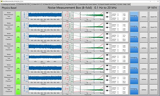
With the Noise Measurement Box (NMB), eight channels of voltage noise can be accurately measured in parallel. It is a plug-and-play USB device and comes with a user-friendly Windows application that makes noise measurements very simple and reliable.
The noise measurement covers a frequency range from 0.1 Hz to 20 kHz, but the actual frequency range can be selected by the user, and the required anti-aliasing LP filters are set automatically. The Fast Fourier Transformation (FFT) is calculated using a data acquisition system with 24-bit voltage resolution. The voltage noise density [V/sqrt(Hz)] and the total integrated noise voltage [Vrms] are calculated and displayed graphically. The display can be easily switched between linear and logarithmic scaling. All data can be saved in a text file and thus imported into any other application.
Thanks to its ultra-low noise AC input amplifiers with a noise density of only 1 nV/sqrt(Hz), noise voltages down to a few nV/sqrt(Hz) can be measured directly.
The eight channels are galvanically isolated from each other to prevent ground loops. The gain of the input amplifiers can be individually adjusted between 100, 1'000 and 10'000.
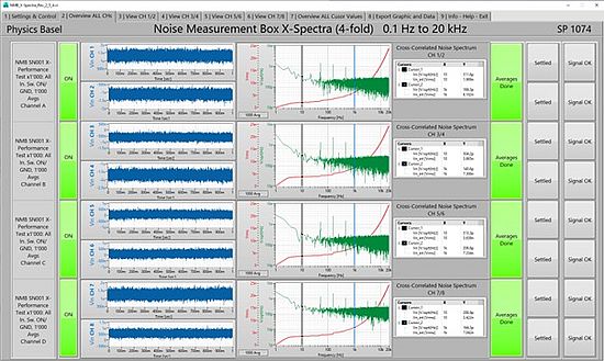
Even lower input noise levels can be achieved by selecting the cross-correlated voltage noise measurement supported by the NMB. By applying a cross-correlated spectral analysis to two adjacent channels, the uncorrelated noise of the preamplifiers can be significantly reduced when averaged over a long period of time. After 1’000 averages the input noise density drops down to around 0.16 nV/sqrt(Hz).
Noise measurements down to low frequencies are very time consuming. Therefore, it is a great advantage to perform noise measurements on multiple channels simultaneously. The NMB's eight parallel channels significantly reduce the time required to perform noise measurements on multiple samples (e.g. semiconductors). If more than eight channels need to be measured, multiple individual NMBs can be connected to a measurement host computer simultaneously.
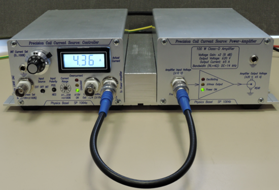
The Precision Coil Current Source (PCCS) is a controllable bipolar current source for coils used in sensitive physics experiments. Such coils are often in Helmholtz or anti-Helmholtz configuration to produce a uniform magnetic field or field gradient. The low drift and low noise performance of the PCCS makes it the ideal choice for operating these coils.
The PI controller of the PCCS can be adapted to almost any coil with an inductance from 0 H (purely resistive) to 2 H. If the coil inductance and its DC resistance are known, the two components (R and C) for the PI controller can be estimated using a small Excel spreadsheet. The estimated components result in an aperiodic set-point behavior with no overshoot. They provide a good starting point for further tuning the control loop for faster response.
The coil current can be up to ±5 A and the maximum output voltage is ±20 V. To achieve the maximum current of 5 A, the DC resistance of the coil must be equal to or less than 4 Ohm. The Class-D power amplifier minimizes the self-heating of the PCCS. The current range can be set from ±1 A to ±5 A in 1 A increments using a rotary switch on the front panel. This allows the PCCS to be flexibly adapted to different current requirements. Therefore, the same system can be used for changing current requirements.
A DC current can be set via the internal multi-turn potentiometer, which is connected to a voltage reference source with low drift and low. A digital meter on the front panel displays the actual DC coil current.
For dynamic control of the coil current an external voltage can be applied whose voltage of ±10 V corresponds to ±100% of the selected current range. To maintain the excellent performance of the PCCS, this external set-point voltage must also have low drift and low noise. Our “Low Noise / High Resolution DAC II (SP 1060)” is an optimal voltage source for the set-point control of the PCCS.

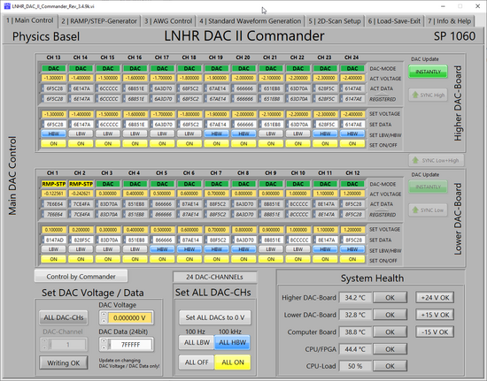
The LNHR DAC II is a precision multi-channel voltage source with excellent low noise performance combined with high resolution (24-bit) and outstanding temperature-drift. It is designed to drive high-ohmic gates or to perform fast two-dimensional (2D) scans in physics experiments on samples cooled to temperatures close to absolute zero. Due to the 24-bit resolution, a voltage step of only 1.2 µV is achieved at the ±10 V DAC output voltages. The common ground of the DAC-outputs is galvanically isolated from the housing and the computer interface; this design efficiently prevents ground-loops.
The bandwidth of each DAC-channel can be individually selected between LOW (LBW=100 Hz) and HIGH (HBW=100 kHz). In the LBW-mode (100 Hz) the output noise is smaller than 500 nVrms, integrated from 0.1 Hz to 890 Hz and in the HBW-mode (100 kHz) smaller than 4 µVrms, integrated from 0.1 Hz to 100 kHz. These excellent noise voltages are achieved over the entire ±10 V DAC output voltage range.
Four individually programmable RAMP/STEP Generators and four Arbitrary Waveform Generator (AWG) are implemented. The RAMP/STEP Generators can be used for autonomous voltage sweeps and for 2D-scans in combination with the AWG. Even adaptive 2D-scans can be easily be generated by this device. Each AWG can store up to 34’000 points with 24-bit amplitude resolution and a freely programmable clock rate up to 100 kHz; external clocking is also possible.
The LNHR DAC II can be used for stable DC-biasing, ramping voltages, two-dimensional voltage scans and low-frequency AWG function. DAC- or AWG-update can be synchronized internally or externally by applying TTL signals on the back of the device.
The LNHR DAC II is available in two versions: 24 or 12 DAC-channels; both versions are housed in a 19”-rackmount case with a height of only 2U (88.9 mm). Because of its great flexibility, this device can also be used as a precision voltage source for a wide variety of applications.
The device is controlled locally by the LCD and the rotary/push knob (encoder) or remotely using the TCP/IP or RS-232 interfaces by sending simple ASCII commands.
The included LabVIEW drivers and sample programs allow easy software integration of the LNHR DAC II into a given measurement environment.
By using the PC Windows application “LNHR DAC II Commander”, the device can be controlled in a user-friendly manner and this software also enables easy setup of 2D-Scans.
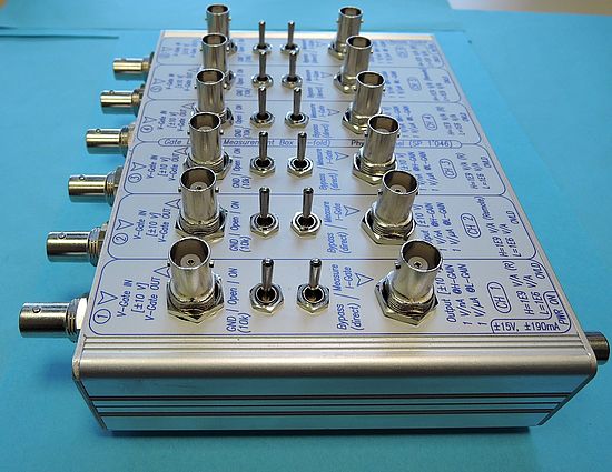
The "Gate Leakage Measurement Box" (GLMB) allows to monitor six gate currents in parallel during a running experiment. By installing the GLMB between the gate voltage source (e.g. LNHR DAC) and the sample, the gate leakage currents can be measured without greatly increasing the noise level and deteriorating the stability of the gate voltage. Gate voltages in a range of up to ±10 V can be precisely current monitored from the pA-range up to the 10 µA-range. This large measurement range is realized by two different current measurement ranges which have a scaling of 1 to 1’000. The bandwidth of the current measurement is 10 Hz and therefore only DC leakage currents can be detected. The six analog output voltages – which are proportional to leakage currents – can be readout by a data-acquisition (DAQ) or by several digital volt-meters (DVM).
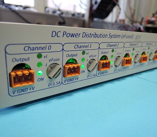
The “DC Power Distribution System” is designed for the low voltage supply of many different electronic devices that are relatively close together. This is usually observed in physics experiments on optical tables where a large number of different electronic devices need to be powered. In such environments, many wall plug-in power supplies are often found or several adjustable laboratory power supplies are used. Such solutions are cumbersome, prone for incorrect voltage settings combined with inadequate current limitation and hard to debug.
For cleaning up the power supply system in physics experiments with many electronic devices the “DC Power Distribution System” is a perfect solution. Each of its ten output channels can be current limited separately (eFused) and the outputs are automatically switched off when an incorrect input voltage is applied. Further, each output channel can be current- and voltage-monitored and switched on/off manually. All these features significantly increase the reliability and the safety of the power supply system.
The "DC Power Distribution System" is available for these standard voltages: ±5 V, ±12 V, ±15 V (±18 V).
Each voltage has its own plug system, which prevents from accidentally confusing the different voltages of an experiment. Please note that the bipolar power supply that must be connected to the back of the "DC Power Distribution System" is not included – it must be selected and purchased by the user.
To download the user manual, please click here.
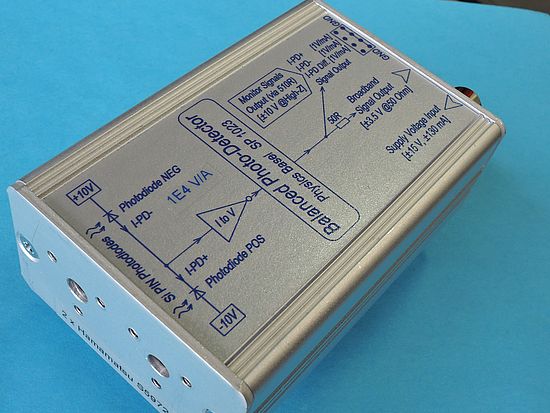
This Balanced Photo-Detector (BPD) combines large bandwidth (50 MHz) with low noise performance. At 1 MHz the typical dark noise density is only 1.7 pA/sqrt(Hz). At a wavelength of 800 nm this corresponds to an optical power noise density of 3.2 pW/sqrt(Hz). At an optical power of 8.3 μW (@800 nm) on both photodiodes, the shot-noise density reaches to the dark noise density. The device is equipped with two large-area (d = 0.8 mm) silicon PIN-photodiodes (Hamamatsu S5972). Those cover an optical wavelength range from 320 nm to 1 μm. At 800 nm these photodiodes have a quantum-efficiency of around 84%. Since the photodiodes are mounted on sockets they can be changed easily. They can also be replaced by other low-capacitance photodiodes, covering different wavelength ranges.
The BPD has a gain of 1E4 V/A and the broadband output signal drives up to ±3.5 V when terminated with 50 Ohm. Several monitor signals (I-PD+, I-PD-, I-PD Diff) are available for DC-readout or slow-control; they are also very handy when setting up and adjusting an optical experiment.
With the M4 mounting-thread at the bottom the BPD can be mounted directly onto an optical table. Since the mounting-adapter is made out of plastics the device remains electrically isolated from the optical table.In combination with the included floating power supply no ground-loops can occur.
The "High-Gain" version (1E5 V/A) of the Balanced Photo-Detector has a better noise performance but a reduced bandwidth of 15 MHz. At 0.5 MHz a typical dark noise density
of only 0.6 pA/sqrt(Hz) is reached; this corresponds to an optical power noise density of 1.1 pW/sqrt(Hz) at 800 nm.
HIGH-GAIN User Manual
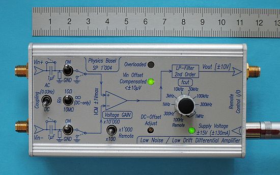
This 1 MHz differential voltage amplifier combines low input voltage noise and low offset voltage drift. This combination is important for long-lasting measurements on samples at cryogenic temperatures. Commercial available amplifiers suffer from higher voltage noise or lower offset voltage stability over temperature and in time.
Low input voltage noise is reached by using a discrete dual J-FET (IF 3602) in the input stage. The offset voltage drift of this low noise J-FET input stage is reduced by a precise servo control-loop. The voltage gain can be switched between x100, x1'000, x10'000 and a variable LP-Filter (100 Hz... 1 MHz) is also integrated. At a gain of x100 an input differential voltage up to ±100 mV can be amplified linearly. The amplifier can be AC or DC coupled, the input resistance can be switches between 10 MOhm, 1 GOhm and infinite (DC-only) and the common-mode voltage can be up to ±1 V. All these features make the Low Noise / Low Drift Differential Amplifier a versatile laboratory preamplifier.
To download the data sheet (SN 001...021) click here.(Version 1.0)
To download the data sheet (from SN 022) click here. (Version 2.2)
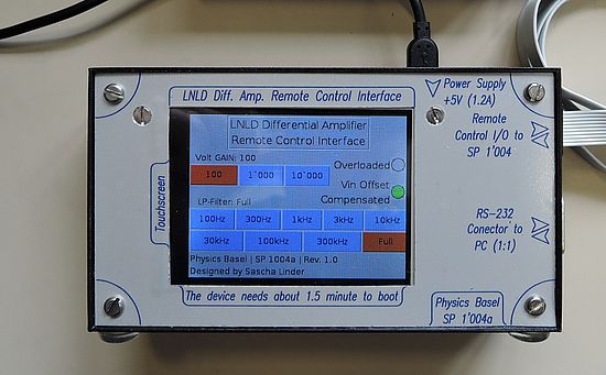
For best performances the Low Noise / Low Drift Differential Amplifier (SP 1'004) should be installed as close as possible to the sample. Optimally it is attached directly to the breakout-box on top of the cryostat which is often hard to access during running experiments. This Remote Control Interface allows controlling the voltage-gain and LP cut-off frequency via a flat-cable with a length of serval meters. In addition, the OVERLOAD and OFFSET-COMPENSATED status of the amplifier is readout by the Remote Control Interface. Since the remote control inputs on the LNLD Differential Amplifier are galvanically isolated by optocouplers no ground loops can occur by using this remote control. The Remote Control Interface comes with a 2.8'' touchscreen for manual control and has a serial port (RS-232) for simple ASCII communication with a computer.
This Remote Control Interface is based on a single-board Raspberry Pi B+ computer running a Linux operation system.
To download the user manual, please click here.
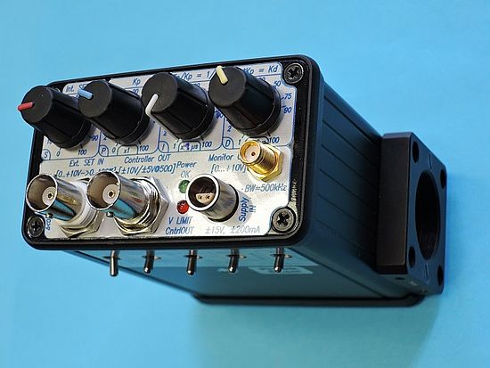
For the intensity stabilization of lasers and other light-sources the Optical Intensity Stabilizationcan be used. The OIS is a tiny box containing an optical detector (PIN-photodiode and amplifier) a PID-controller, a stable reference value and a 50 Ohm driver unit. The versatile OIS-box can be mounted directly onto an optical table with an M4 thread. The large area (7 mm2) photodiode is mounted in the center of a 30 mm cage plate (SM1, CP02/M from Thorlabs) and has a bandwidth of 500 kHz. It is suitable for wavelengths in a range from 400 nm to 1'100 nm.
To download the user manual, please click here.
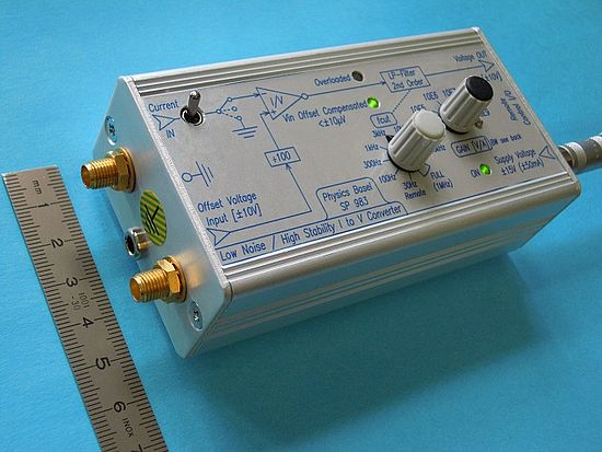
The LNHS I to V Converter combines low input voltage noise with high stability and low drift input voltage (< ±0.2 μV/K). This combination is very important for measurements on samples at temperatures near the absolute zero. Commercial available I/V converters suffer from higher input voltage noise or lower input voltage stability over temperature. The gain can be selected in decades from 105 up to 109 V/A and the low-pass filter can be adjusted between 30 Hz and 100 kHz. These settings can also be done remotely by using the Remote Control Interface (SP 983a). At the maximum gain (109 V/A) the bandwidth is typical 1.6 kHz and at the minimum gain (105 V/A) reaches 600 kHz. By applying an external voltage the input offset voltage can be varied within ±100 mV.
The device can be equipped with two different J-FETs in the input stage:
1) STANDARD: LSK389A
PRO: Lower input current noise (significant in the 108 and 109 V/A ranges)
CON: Slightly higher input voltage noise. Smaller gain-bandwidth-product (68 MHz) increases output noise at large input-capacitances.
2) HIGH-GBWP: IF3602
PRO: Slightly lower input voltage noise. Lager gain-bandwidth-product (620 MHz) makes output noise significant smaller at large input-capacitances.
CON: Higher input current noise (significant in the 108 and 109 V/A ranges)
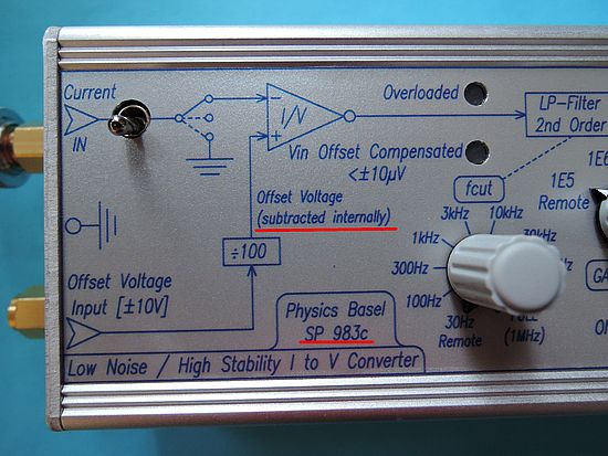
The version SP 983c of the "LNHS I to V Converter" is completely the same as the SP 983 above, only that the external applied input offset voltage is internally subtracted and is no longer on top of the output signal.
This option was demanded by users sweeping or altering the input offset voltage of the "LNHS I to V Converter".
The device can be equipped with two different J-FETs in the input stage:
1) STANDARD: LSK389A
PRO: Lower input current noise (significant in the 108 and 109 V/A ranges)
CON: Slightly higher input voltage noise. Smaller gain-bandwidth-product (68 MHz) increases output noise at large input-capacitances.
2) HIGH-GBWP: IF3602
PRO: Slightly lower input voltage noise. Lager gain-bandwidth-product (600 MHz) makes output noise significant smaller at large input-capacitances.
CON: Higher input current noise (significant in the 108 and 109 V/A ranges)
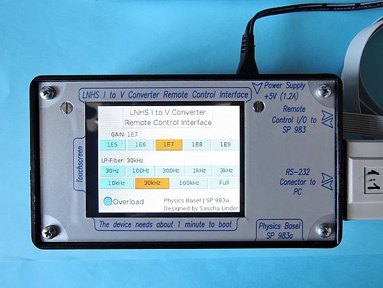
It is recommended to install the Low Noise / High Stability I to V Converter (SP 983) as close as possible to the sample. Therefore the I/V converter is often located in a places hard to access during running experiments. This Remote Control Interface allows for the remote control of the gain and LP cut-off frequency via a flat-cable with a length of serval meters. Since the remote control inputs on the LNHS I to V Converter are galvanically isolated by optocouplers no ground loops can occur. The Remote Control Interface comes with a 2.8'' touchscreen for manual control and has a serial port (RS-232) for simple ASCII communication with a computer.
This Remote Control Interface is based on a single-board Raspberry Pi B+ computer running a Linux operation system.
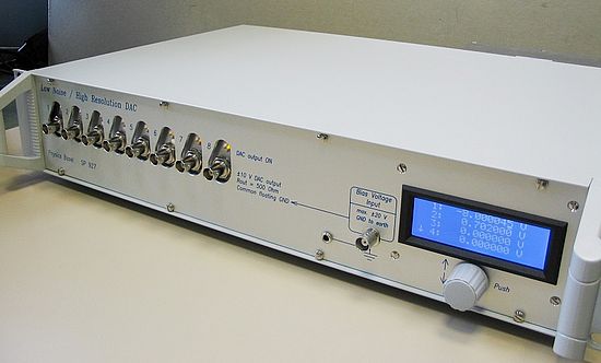
The LNHR DAC is an eight channel voltage source with exceptional low noise performance and high resolution. It is designed to drive high-ohmic gates with ultra-stable voltages in fundamental physics experiments at cryogenic temperatures. For such experiments constant DC bias-voltages and high resolution sweep-voltages with very low fluctuations are mandatory. The output range of ±10 V, combined with the 24 bit resolution, allows adjusting the voltages with a step size of only 1.2 μV. The output voltage noise is below 1 μVRMS, measured in a frequency range of 0.1 Hz to 100 Hz. With its bandwidth of DC…70 Hz the LNHR DAC can be used for DC-biasing, for ramping/sweeping and for low frequency waveform generation. The device can be controlled locally by the rotary/push knob (encoder) or remotely by using the RS-232 interface. The actual voltages can be displayed on the LCD.
User Manual 2.6 (from serial number 0051)
For fast switching between two output channels of the LNHR DAC use the Analog Selector Switch (SP 944). To generate precise voltages up to ±100 V use the HV-Amplifier (SP 908).
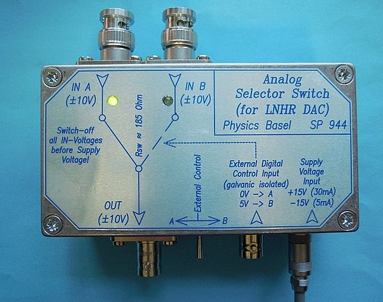
The Analog Selector Switch allows fast and low-glitch switching between two analog voltages in a range of up to ±10 V. To prevent from interferences and ground-loops the TTL-compatible control input is galvanically isolated by an optocoupler. The low noise performance combined with the low ON-resistance (<200 Ohm) and a charge-injection smaller than 1 pC makes this switch suitable for high-sensitive physics experiments. The device can be mounted directly to the BNC connectors on the front-panel of the LNHR DAC (SP 927) and allows fast switching (up to 100 kHz) between two different low noise output voltages.
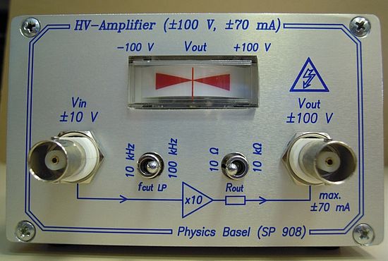
If the standard ±10 V voltages, generated from the LNHR DAC (SP 927), are too low the HV-Amplifier with a voltage gain of ten can be used. It has an output voltage of up to ±100 V with a maximum output current of ±70 mA. To prevent from ground loops, the analog in/out are floating and not referenced to the ground/earth carried by the 230 V mains. An analog voltage-indicator on the front-panel shows the actual output voltage. The device can be used to drive capacitive-loads such as piezo-electrical crystals. The bandwidth can be switched between 10 kHz and 100 kHz; this makes it compatible with the Analog Selector Switch (SP 944).
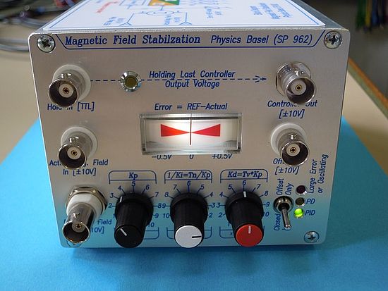
The Magnetic Field Stabilization allows fast and precise controlling/stabilization of the magnetic field at certain location of the experiment. By using a magnetometer (e.g. from Bartington) the actual magnetic field is measured and a Helmholtz-coil driven by an external low-noise current source is used to control the field. The device is installed between the magnetometer and the coil driver current source. For controlling/stabilization of all three space axes three such devices are needed. The PID controller can be adjusted by potentiometers on the front-panel. For fast and precise switching the magnetic field the device automatically changes between PID- and PD-controller, depending on the output voltage of the coil driver current source. This reduces the switching-time of the magnetic field without over/under-shooting by more than a factor two.
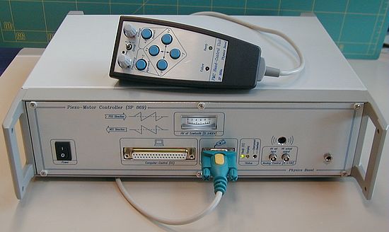
The Piezo-Motor Controller offers the flexible and robust operation of up to eight slip-stick piezo-motors. It allows a bidirectional movement in up to eight axes (channels), whereas only one axis can be driven at the same time. The PMC can drive a wide range of piezo-motor capacitances up to 15 nF. The saw-tooth output voltage of the PMC has a fast back-jump (slip) rise/fall time of only 1 μs at a load-capacitance of 10 nF. This leads to efficient and reliable operation of slip-stick piezo-motors also at cryogenic temperatures. The applied saw-tooth voltage can be adjusted from zero up to ±400 V and the frequency from 1 Hz up to 4 kHz. The PMC can be operated by the Hand-Control Unit (SP 869a) or via a computer-control interface.
Contact
Electronics Lab
Departement of Physics
University of Basel
Klingelbergstrasse 82 (Offices: 2.17 & 2.21)
4056 Basel, Switzerland
T +41 (0)61 207 37 22
F +41 (0)61 207 37 84
Head Electronics Lab
Team
Quick Links
